Composite tooling dictates final part performance, longevity, and cost. Before a single carbon ply hits the mold, the choice of composite tooling materials, the surface finish, and resin flow is taken into consideration. Shops that manufacture advanced composites experience this every day: pick the incorrect material, reinforcement, or draft angle, and you'll suffer inconsistent laminate quality or loss of tool life. Pick right and the part pops free, repeatable, light, done.
Composite tooling manufacturers worry less about theory and more about surface finish, vacuum paths, and how many shots a mold can take before it drifts. That’s why a dedicated carbon fiber composite mold production pipeline – fiberglass shells for prototypes, metal for heat, carbon/epoxy for autoclave work – matters. Get the foundation right and everything downstream gets easier: layup, cure, trim, inspection.
At AMC Composites we run the full stack – from mold design and machining to lay‑up, cure, and inspection, so the tool and the part evolve together. That lets us pick what works, not just what’s on the shelf, and keeps projects on spec, on cost, and on schedule.
Because the tool is the part’s first environment, temperature swings, resin shrink, and fiber spring-back don’t care about intent; they follow the mold. Composite tooling sets:
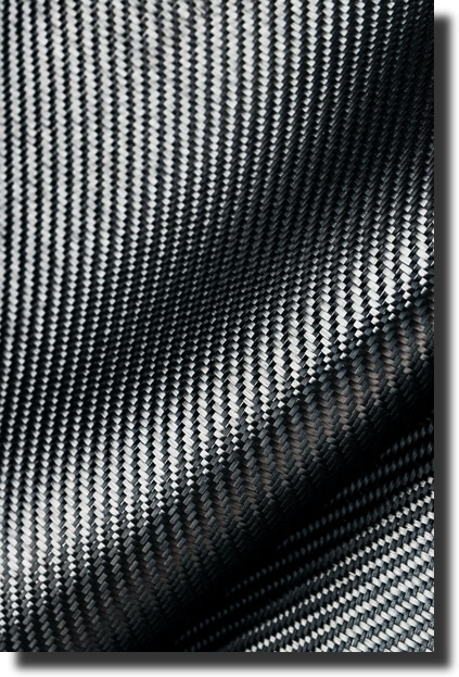
Here is the real difference between fiberglass and carbon fiber at the tool stage: fiberglass molds are cheap and forgiving, perfect for short runs. Carbon/epoxy and metal tools hold tight tolerances at cure temperatures but cost more up front. That trade is exactly where composite and metal tooling materials earn their keep.
For composite tooling manufacturers, success is measurable: fewer shims at assembly, less post‑trim, no rework after cure. The mold is not a bystander. It is the first component you build and the last one you should cheap out on.
If you want the academic backbone behind that cause-and-effect, skim “Fundamentals of Composites and Their Methods of Fabrications”. It shows how reinforcement, matrix, and interface behavior all trace back to the tool that shaped them.
Choosing the right mold type and material is step one of smart composite tooling design. Below are the three standard materials we reach for when manufacturing advanced composites.
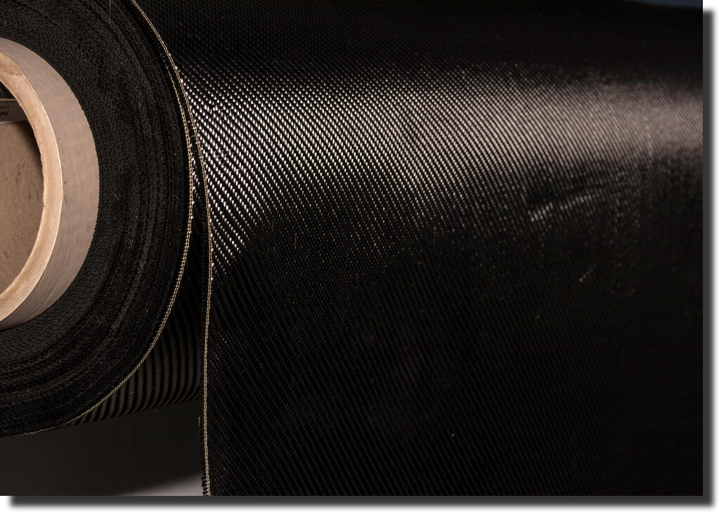
We match the mold material to the cure window and cycle count. Carbon/epoxy shells are the lightest high-repeat option – their low CTE keeps surfaces true, and they heat and cool quickly through hundreds of autoclave shots.
For prepreg programs that run at elevated pressure, we machine steel or aluminum blocks to lock in geometry for the long haul. Tooling board bridges the gap for medium- to high-volume runs where dimensional stability outweighs raw-material cost. Using the right platform keeps fiber architecture consistent, trims ramp energy, and leaves almost no post-machining.
Forged-carbon components follow a different path. The chopped-fiber charge is compression-molded in precision-machined metal tools – typically hardened steel – to provide the tonnage and mirror finish that process demands. Steel takes the pressure; forged carbon delivers the strength and signature marble aesthetic.
If you’re weighing carbon-fiber molds for demanding applications – or need steel tooling for forged-carbon production – contact us and we’ll map the best solution to your budget.
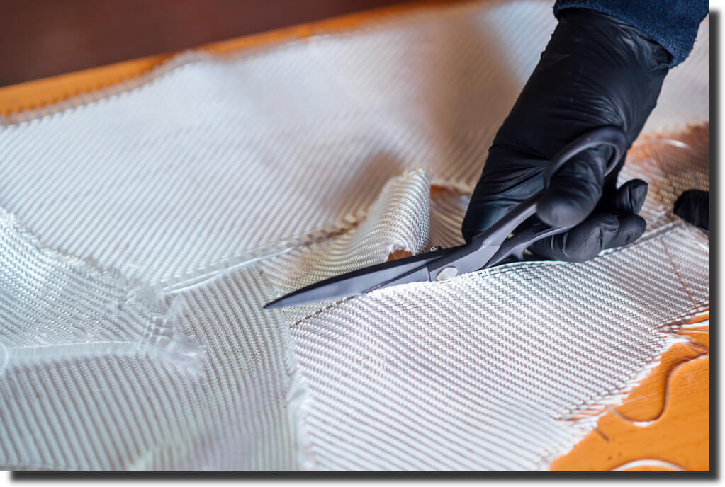
For prototype runs,room-temperature cures, or low-volume oven cures, fiberglass molds are the most cost-effective option: fast to lay, easy to repair, and accurate enough for low to mid volumes. Kevlar steps in when you need a tougher shell that resists chipping or impact during demold.
Both fit neatly into advanced composite tooling when you pair them with smart vacuum routing and stable backing structures. AMC Composites has extensive experience producing fiberglass components.
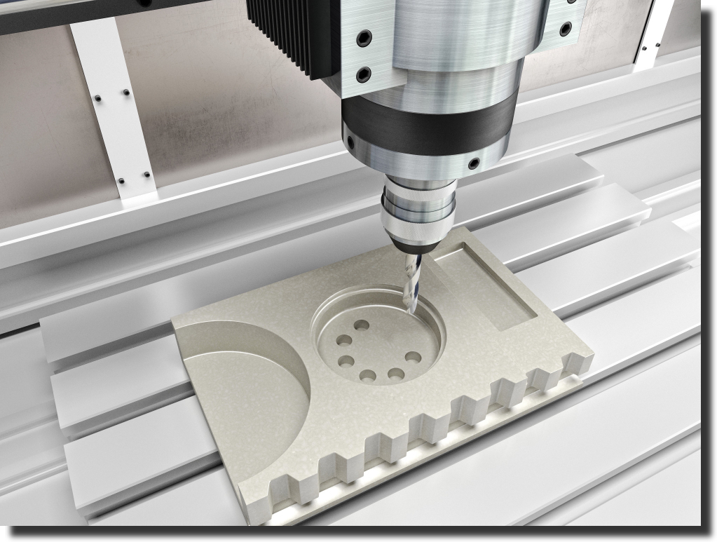
Rapid-turn CNC tooling compresses the entire production loop. CNC-machined polyurethane-foam plugs are sealed the same day, so molds start from final geometry immediately. Because the molds hold tight tolerance shot after shot, engineers can adjust ply drop-offs or bead radii without shifting the schedule. The result is fewer last-minute reworks and lower scrap.
We primarily use SolidWorks and Autodesk Alias to generate detailed models for mold production and for component assembly and design.
Upfront rigor keeps surprises out of the press. Our in-house Design for Manufacturability (DFM) weaves these steps into the part model.
Up-front accuracy in CAD and machining shortens every downstream step, turning the mold into the first critical component of the finished assembly.
Use these filters in order; they narrow choices fast and keep composite tooling decisions tied to data.
Composite tooling is the first part you build, and it decides how every carbon fiber or fiberglass panel will behave. Match the tool material to cure temp, cycle count, and surface demands. Keep design-for-manufacture in the conversation early, and iteration stays cheap.
If you’re weighing options or need to pressure-test a path, see how our services can advance your project – we’ll map your requirements to the right tool stack and get you cutting chips, not corners.
.webp)