Modern parts are lighter, more compact, and increasingly complex, while time-to-market pressures mount. For composites, metals, and hybrid structures, it is essential to ensure designs are realistic for existing tools, machines, and budgets – not simply impressive in CAD.
Ignoring manufacturability at the design stage leads to extra iterations, scrap, rework, and delays. At AMC Composites, we move that thinking upstream so the first production-ready design matches real manufacturing methods, materials, and constraints. The key takeaway: addressing manufacturability early saves time and resources through fewer costly revisions.
Practically, design for manufacturability means building process, tolerances, and quality into the design from the start.
In composites and advanced manufacturing, research in the Composite Structures Journal shows that if fiber paths, curvature limits, and spacing constraints are not included during design, “as-manufactured” properties can diverge from “as-designed” predictions. DFM treats manufacturing constraints as core design inputs, closing that gap.
Engineers often ask what DFM is in day-to-day work – in practice, it means checking at least four things for every new part:
Done well, DFM transforms an attractive model into a part that can be produced repeatedly at scale, without hidden costs or unexpected behavior once it reaches the shop floor. The critical point: designing for manufacturability ensures both consistency and cost predictability.
Decisions made at the CAD stage quietly lock in most of a part’s lifetime cost. Wall thickness, joint style, fiber layout, and process route all determine the number of operations required, the complexity of the tooling, and the level of variation that will occur once production begins.
Design for manufacturability and cost means using a single strategy: each design choice is judged for both performance and production efficiency. That’s where real savings occur:
Modern optimization tools create efficient shapes and fiber layouts, but equipment limits on curvature, spacing, and tool motion pull manufactured parts away from the ideal. DFM keeps those constraints in the design loop, not as add-ons.
DFM acts as the bridge between the optimized model and the real process. Instead of reworking parts after the first trial run, those manufacturing limits are built into the geometry, fiber layout, and stack-up from the start.
For continuous fiber and advanced composite routes, a few simple constraints drive most of the behavior:
Putting these bounds directly into the design workflow keeps the “as-manufactured” stiffness and strength closer to the “as-designed” predictions.
When tolerances, fiber orientation limits, laminate thickness, and minimum cross-sections are treated as core design variables, stiffness, strength, and life become more predictable.
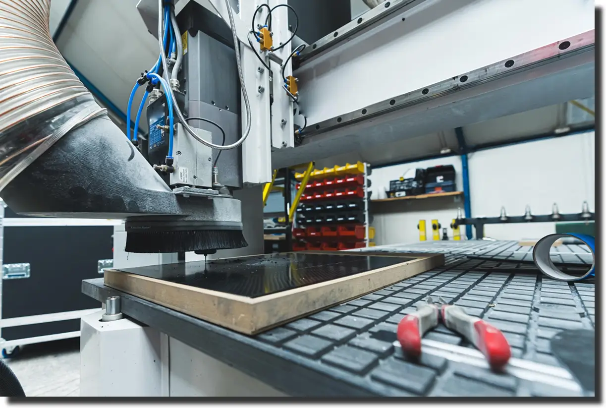
At AMC Composites, we assess both analytical results and practical production steps – machining, lay up, molding, trimming, and inspecting – on our equipment before finalizing the model.
For every new project, we start with a simple checklist:
This provides us with the context to select a route that is both mechanically and commercially sensible.

Based on that context, we select between composite, metallic, or hybrid solutions and match them to the right process route. This can involve compression molding, automated fiber placement, additive manufacturing, CNC machining, or a combination of these methods.
The key is that the design is built around the chosen process – fiber angles, wall thicknesses, radii, and joint details are set with real press pressures, tool limits, and layup strategies in mind, rather than being added as an afterthought.
To keep the part practical on the shop floor, we deliberately design around:
In this phase, our In-House Design Capabilities, Tooling & Machining Services, and Custom Carbon Fiber Parts integrate into a seamless workflow that avoids unnecessary handoffs.
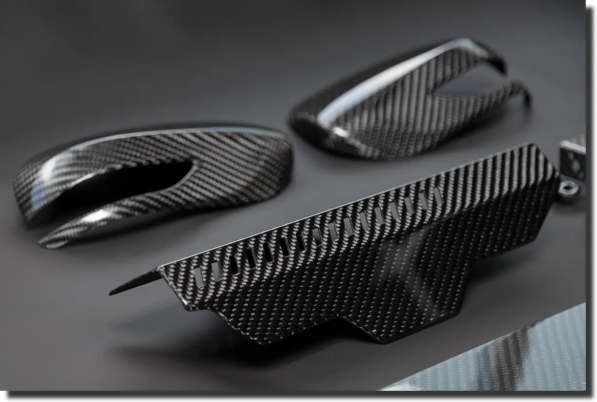
By involving AMC Composites early, teams avoid costly redesign loops, schedule slips, and hidden costs in tooling revisions, scrap, and rework. This holds for small brackets, complex housings, or Carbon Fiber Wheels. Our carbon fiber DFM approach consolidates fiber paths, tooling limits, inspection, and field loads into a shared model, rather than separate checklists.
Best practice is to pull DFM in before problems show up on the shop floor. Typical trigger points:
Design for manufacturability is a practical approach to creating a product that can be built at scale, is stable in quality, and remains economically viable throughout its entire life. It links geometry, materials, and process so that the part that leaves the tool behaves like the part you analyzed.
If you are interested in reviewing a design before committing to tooling, AMC Composites can review your part, suggest DFM improvements, and help map the optimal route from concept to production.
.webp)