Forged carbon addresses two demands that keep rising: engineering teams need complex geometries, and manufacturing teams need them produced quickly and consistently at volume. That’s why wheels, suspension components, brackets, housings, and structural covers are increasingly specified in forged carbon.
Across the global carbon fiber supply chain, demand continues to rise as automotive, aerospace, energy, and infrastructure move toward lightweight, high-performance materials. Higher volumes mean OEMs and tier suppliers need processes that scale: not just more carbon fiber, but routes that can deliver thousands of near-net-shape parts without compromising mechanical performance.
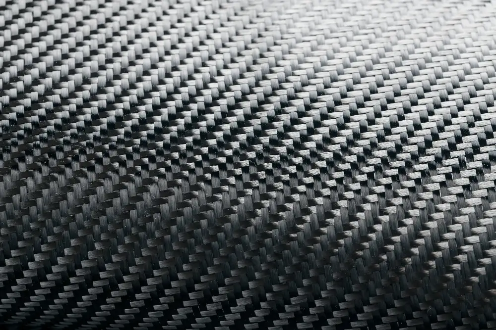
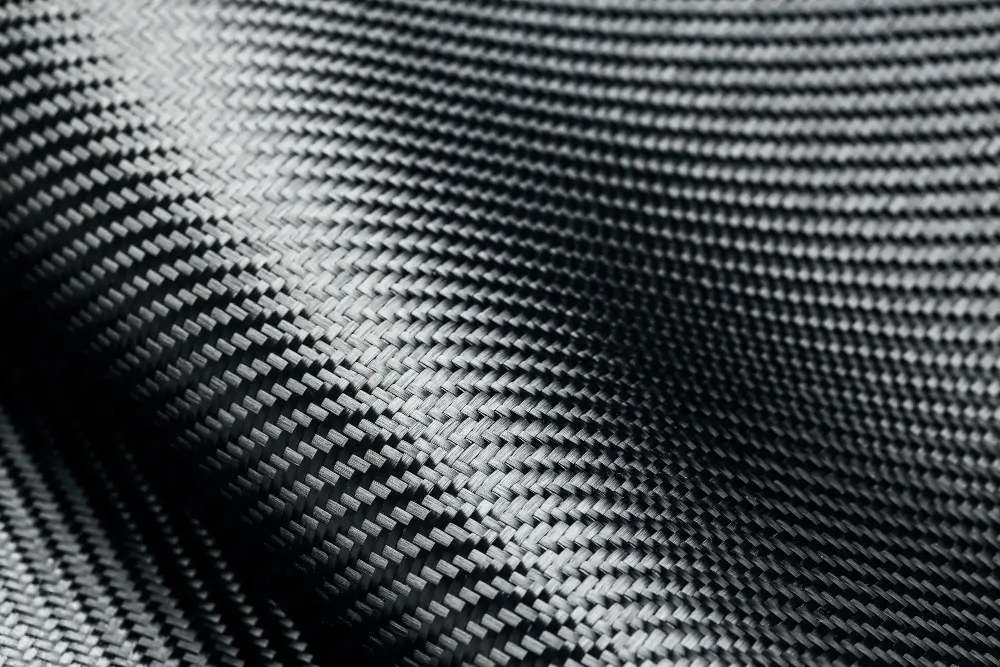
For us, forged carbon sits alongside prepreg layup, vacuum Infusion explained, and wet layup as a manufacturing method used to meet specific application requirements. Continuous plies and autoclave cycles are still the answer for thin skins and class-A surfaces; Carbon Fiber vs Fiberglass remains the baseline comparison for many programs. When the brief shifts toward intricate geometry, tight packaging, and high-volume production, forged carbon becomes the natural candidate in that same toolkit.
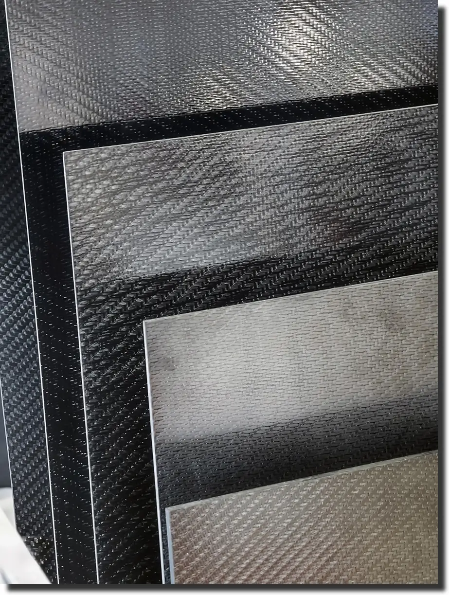
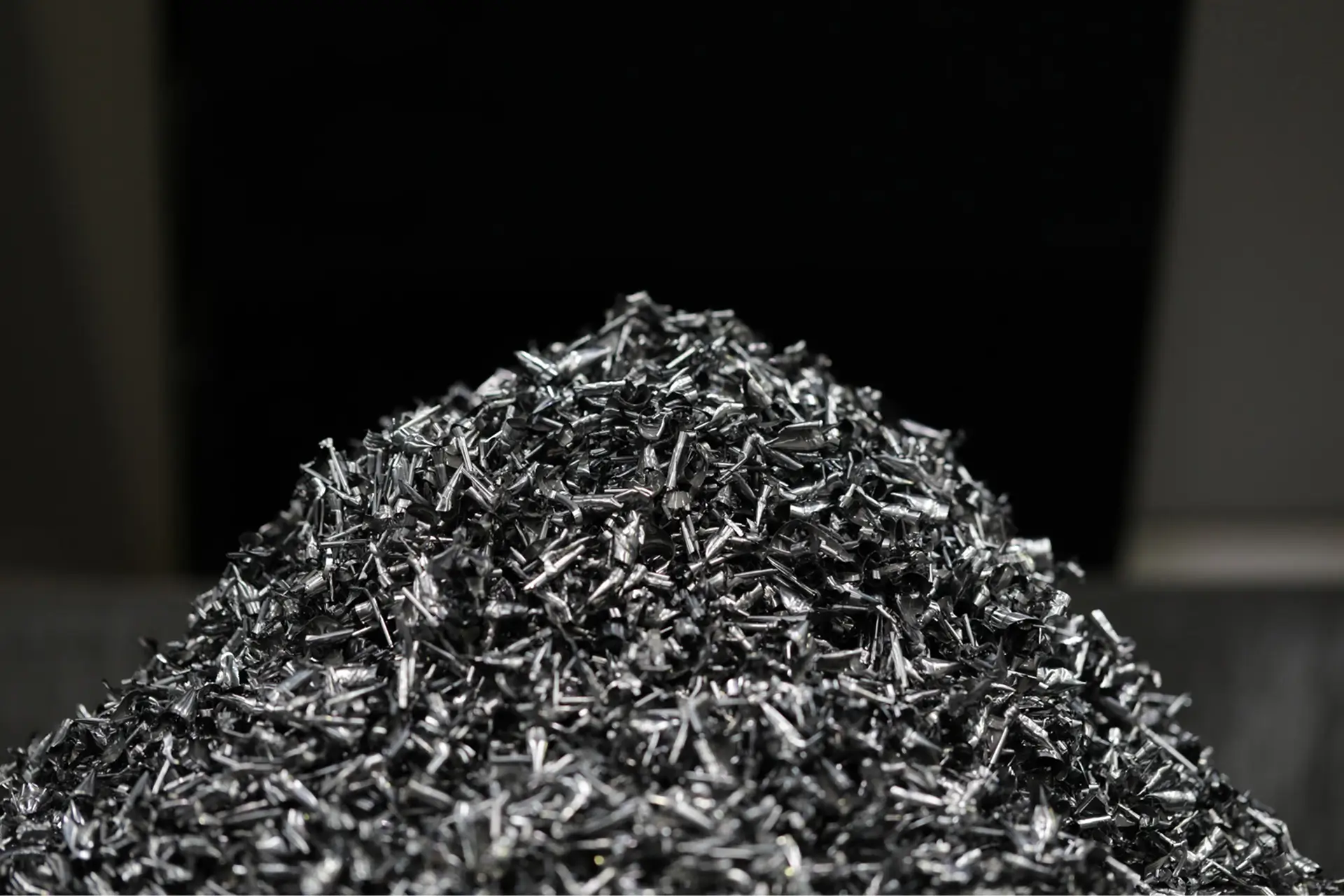
When we talk about forged carbon fiber, we are not just naming a different weave pattern; we are describing a different form of material and a different way of molding it. Instead of stacking continuous fabric plies, the process starts with chopped carbon fiber – often derived from prepreg or tow – pre-mixed with resin into a charge. That charge is placed into a matched metal tool, the mold closes under pressure, and heat drives the cure.
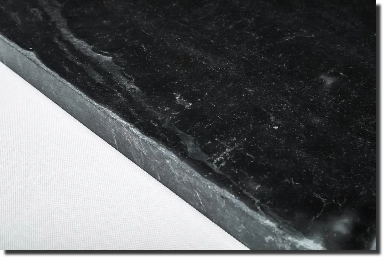
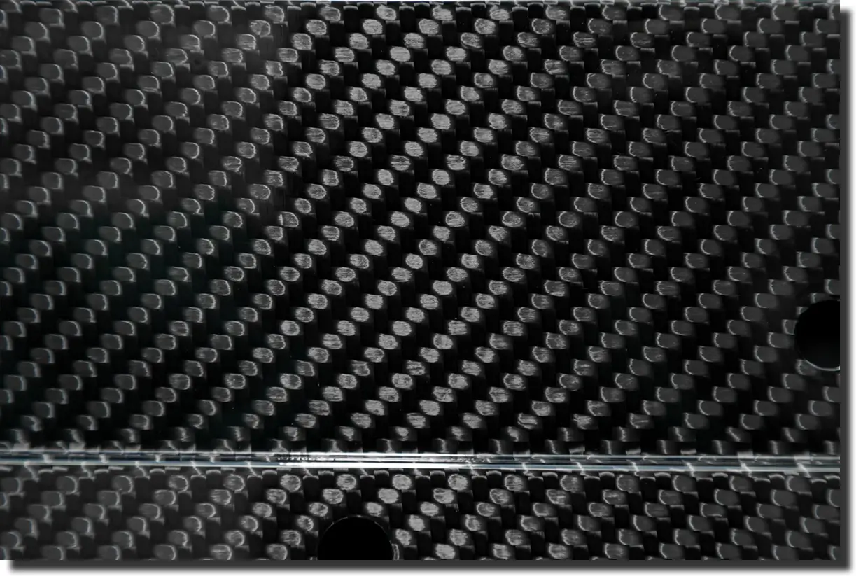
The result is a solid composite with randomly oriented fibers and a characteristic marbled surface. In a classic layup, fibers run in defined directions (0/±45/90°), and mechanical properties follow those directions; stiffness and strength are highest along the main fiber axes, and weaker off-axis behavior has to be managed in the stack design. In a forged-style compression molding route, chopped fibers pack into ribs, pockets, and tight radii in many directions at once, giving more quasi-isotropic behavior in the plane of the part.
At the process level, forged carbon belongs to the same family as carbon-fiber sheet molding compounds (CF-SMC). A charge with a controlled fiber volume fraction is compression-molded to fill the cavity, consolidate, and cure in a single cycle.
The approach has been documented widely in the composites literature; a recent study on carbon fiber composites in Composites Part B is one example of how industry and research are pushing high-volume, high-performance manufacturing routes forward. Against that backdrop, forged carbon is simply the practical implementation: chopped carbon, a matched metal tool, and a press cycle tuned to the geometry and duty of the part.
When asked how forged carbon fiber is made, we usually break it into four simple stages: feedstock, mixing, compression molding, and finishing. Each step is tuned so the charge flows into every rib and pocket, cures cleanly under pressure, and comes out of the tool as a dense, repeatable part.
In a matched-metal tool under heat and pressure, the process behaves more like a sheet-molding route than a traditional hand layup. That makes forged carbon a strong fit when geometry is complex, production volume is high, and cycle time matters as much as strength.
Most forged programs start from familiar inputs: carbon fiber prepreg and tow feedstock. Continuous material is slit and chopped into short lengths, then combined into a bulk charge that can flow when heated and pressed. The fiber length is chosen to balance flow into tight features with the stiffness and strength the part needs.
In some cases, recycled or offcut material can be reprocessed into a forged-style feedstock. That aligns with broader industry work on carbon fiber recycling and closed-loop use of composites, where chopped fibers from retired parts or trim waste are redirected into new high-value components instead of scrap.
The next step is turning chopped fiber into a moldable “paste.” Fibers are combined with a thermoset resin system – most often epoxy, sometimes vinyl ester – at a controlled fiber-to-resin ratio. The goal is to load enough fiber to hit mechanical targets while still letting the charge flow across the mold at pressure.
Depending on the application, additives and pigments can be introduced at this stage to tune flow, toughness, or appearance. For structural parts, we target a consistent, void-lean mix that will wet the fibers thoroughly under heat and pressure; for visible components, resin clarity and pigment dispersion matter just as much as bulk properties.
Once the charge is prepared, it is placed into a preheated mold cavity and the press closes. Under pressure – often in the hundreds to low thousands PSI, and temperatures in the 250-350 °F range, the resin softens, flows, and wets the chopped fibers as the material is forced into the tool cavities.
As the temperature profile holds, the resin cures and the composite consolidates. Voids are squeezed out toward vents or non-critical regions, and the random fiber network locks into place. A well-tuned compression molding cycle parameters set keeps cure time short while delivering stable thickness, low porosity, and repeatable mechanical behavior from part to part.
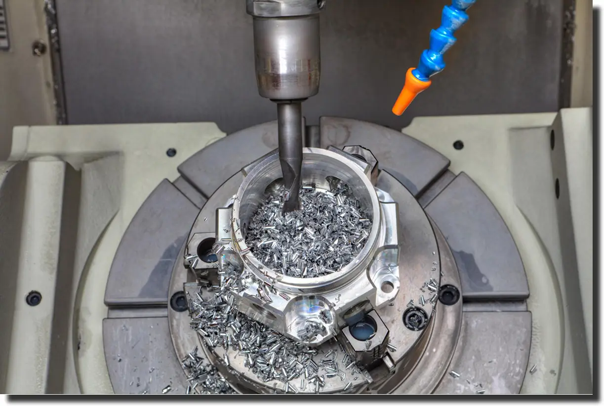
After the cure is complete, the press opens, and the part is released from the tool. Edges, gates, and flash are removed in a trim operation, and any critical surfaces are machined to final tolerance. Depending on how the component will be used, it may receive a clearcoat, paint, or textured finish to protect the surface and control appearance.
On new programs, we usually run forged parts through the same prototyping and development services we offer for other routes: short trial runs, dimensional checks, and functional testing before scaling tooling and press time. That loop lets us validate that the forged charge, mold design, and cycle settings are aligned before the part moves into true high-volume production.
When we talk about forged carbon fiber strength, we are really talking about how a chopped, randomly oriented laminate behaves under real loads: bending, impact, torsion, and millions of cycles in service. The material trades some directional efficiency for a more balanced response and builds that balance into a process that repeats cleanly at volume.
In a traditional laminate, fibers run in defined directions, so stiffness and strength are highest along those axes. Off-axis, the laminate relies on matrix and secondary plies, and local peaks around holes and edges have to be managed carefully. Forged carbon spreads fibers in many directions at once, so brackets, housings, and hubs see a more quasi-isotropic load response in the plane of the part.
That balanced behavior is helpful when the load path is not simple. Complex brackets, knuckles, and forged carbon fiber wheels see combined bending, torsion, and impact. In those cases, the random architecture helps soften stress concentrations and carry load through multiple fiber paths instead of a few dominant directions.
The trade is efficient. A well-designed continuous laminate will always win along its primary fiber directions for minimum thickness and mass. Forged material spends some of that efficiency to gain flow into ribs and pockets, better behavior under multi-directional loading, and shorter press cycles. Where geometry and volume dominate the brief, that trade often makes sense.
Compression molding gives direct control over how much fiber sits in the part. Charge weight, mold volume, and press conditions are tuned so the material fills the cavity, expels excess resin, and consolidates to a stable fiber volume fraction. That helps keep stiffness and strength in a predictable window across multiple tools and presses.
Forged parts are often slightly denser than an ultra-optimized continuous laminate at the same envelope. The chopped architecture and tight packing add a little mass, but in return, the part holds shape under load, tolerates complex geometry, and carries fewer voids when the cycle is well tuned. For components that see real service loads instead of lab coupons, that consistency matters more than chasing the last gram.
A simple way to think about it:
It’s easiest to think about fatigue and impact in forged carbon in a few simple points:
When we design forged carbon fiber parts at AMC Composites, we treat them like any other structural route: start with the load case, geometry, how the part fits into the rest of the system, and production volume. From there, we decide whether forged is the primary process or one piece of a hybrid design.
Our in-house team uses the same workflow you see in our Design & Development Services: define use case, model how it will be used, then determine material, process, and tooling.
Forged carbon is the route we reach for when shapes are complex, volumes are high, and press time matters as much as mass. If you are still asking how forged carbon fiber is made, the practical answer is simple: chopped carbon, a tuned resin system, and a controlled compression molding cycle in a matched tool.
Because AMC runs forged, prepreg, infusion, and machining under one roof, we can match the process to the print instead of forcing a part into a single route.
If you want to sanity-check a concept or map geometry, volume, and load case to the right process, contact AMC Composites.
We can review your print and propose a path that fits both performance and production.
.webp)