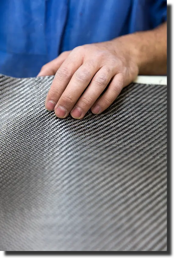
Carbon fiber parts are popular because they offer high stiffness with low weight. This stiffness is not just a property of the material itself. It results from design choices, starting with the modulus of elasticity and including the laminate, tooling, and quality plan used in production.
A high modulus of elasticity is what keeps a carbon fiber bracket from sagging under load, a carbon fiber housing from losing alignment as temperature changes, and a carbon fiber wheel from feeling compliant under cornering loads. It is also one of the first properties that forces a real decision on fiber grade, layup architecture, and process route.
At AMC Composites, we treat this as the bridge between design intent and manufacturing reality. If a part has tight deflection limits, packaging constraints, or a high cycle duty, modulus drives more of the work than many teams expect.
The carbon fiber modulus of elasticity describes how strongly a composite resists elastic deformation in the linear range, before damage or nonlinearity dominates the response. For many carbon fiber components, deflection control is the real requirement, even when specifications emphasize strength.
Modulus is important because it affects both how a part feels to customers and what engineers can measure right away:
This is why modulus decisions show up early on programs like custom carbon fiber parts, structural covers, carbon fiber mounts, and carbon fiber wheels. If the load path is clean and directional, fibers can be placed to deliver stiffness where it is needed. If geometry is complex or loading is multidirectional, modulus becomes a system problem that includes laminate schedule, thickness, local reinforcement, and process consistency.
Modulus of elasticity is the slope of the stress strain curve in the linear elastic region. In practical terms, it describes how much stress is required to produce a given elastic strain, before permanent damage or nonlinear behavior becomes permanent.
For carbon fiber composites, modulus is not a single universal value. It depends on load direction, fiber orientation, and laminate quality. A unidirectional laminate can be very stiff along the fiber direction and far less stiff off axis. A quasi isotropic layup spreads stiffness across directions, but it will not match a directional laminate along a primary axis at the same thickness.
Carbon fiber is also anisotropic at the fiber scale, and some high modulus grades can show stiffness variation across the fiber diameter. Research on high modulus carbon has documented a skin core structure in certain PAN based fibers, with the outer region behaving much stiffer than the core under localized testing. The engineering takeaway is straightforward. Composite behavior should be validated at the laminate and part level, not assumed from a single headline number.
Stiffness and strength are connected, but they solve different problems.
A part might be strong enough but still fail if it bends too much. This often happens in long spans, thin panels, or parts that connect to hard points and hardware. The best approach is to set both a deflection limit and a safety margin, then design the laminate and thickness to meet both, using a process that can be repeated in production.
Modulus is more than just a number on a fiber datasheet. It comes from the choice of fiber, the way the laminate is laid up, and how well the composite is formed in the mold.
Various fiber types are available for different stiffness levels. When stiffness is the main goal, teams look at higher modulus options and check strain limits for the specific load. This is where the modulus of elasticity of carbon fiber helps narrow down design choices.
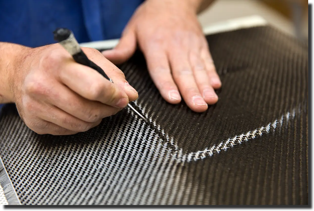
At the laminate level, stiffness depends on how much fiber is actually carrying the load and how well the laminate is made.
A unidirectional laminate is very stiff along its main axis, but the stiffness needs to match the actual load path. Quasi-isotropic layups give more balanced stiffness, which is useful for brackets, covers, and housings with loads from different directions. The trade-off is reduced lay up efficiency compared to a layup designed for one load direction.
The carbon fiber composite modulus of elasticity in a real part is the result of laminate and geometry working together. Two parts can use the same material system and still feel very different because load paths and boundary conditions differ.
Stiffness changes greatly with part geometry. Even minor changes in thickness, rib height, flange width, or curve can affect deflection more than changing the fiber grade.
Common stiffness drivers at the part level include:
If stiffness is critical, the quickest path is to address these factors first:
Using the same fiber and resin does not guarantee the same stiffness. The manufacturing process controls how consistently stiffness is achieved across a laminate. Each process manages fiber placement, fiber volume, and void content differently. That process control is what makes carbon fiber elastic modulus repeatable in production.
Prepreg allows for precise control of fiber alignment and resin content. It’s a reliable method when you need stiffness in a certain direction and need consistent results.
Infusion and wet layup can make great parts if flow and consolidation are well managed. The main risk is uneven resin content or incomplete wetting if the process isn’t matched to the part’s shape.
Compression molding works well for complex shapes and higher production volumes. It gives up some directional stiffness to better fill features and control cycles, especially for parts with ribs, bosses, or tight spaces.
After molding, steps like trimming and assembly can either keep the part stiff or make it more flexible in certain spots. The quality of holes, edges, and how inserts are installed all affect stiffness in critical parts.
Stiffness targets are only useful if the finished parts are uniform from shot to shot. We treat stiffness as a system requirement and manage it from design to inspection in one smooth process.
We like to get involved early so the laminate plan and process fit the part’s shape. Design for manufacturability (DFM) looks at part complexity, assembly, material choices, and process improvements before making tools.
We support CAD modeling, structural analysis, and reverse engineering using 3D scanning and metrology. This reduces iteration and confirms designs are built around real boundary conditions.
We ensure consistent stiffness at every step:
This is how we manage the modulus of carbon fiber composites in each part.
Modulus is the key to stiffness in carbon fiber design. If you want parts that keep their shape, feel solid, and can be made consistently, you need to link modulus targets to layup, shape, and process control.
AMC Composites can help you every step of the way. If you want to review a drawing, check deflection targets, or pick a manufacturing method that delivers consistent results, contact our team. We’ll suggest a practical plan that fits your part’s shape, load, and production needs.
.webp)