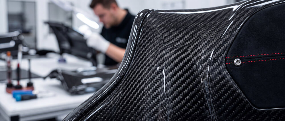
A molded carbon fiber part is rarely ready for assembly the moment it leaves the tool. Flash may need to be removed, edges still have to reach final dimensions, and holes, cutouts, or mounting features may need to be added before the component matches the print.
That is why machining carbon fiber is part of the manufacturing plan, not a cleanup step at the end. Cutting, drilling, and milling have to establish finished geometry without damaging the laminate around the feature being created. The requirements can change significantly between flat panels, structural covers, housings, carbon fiber wheels, and other custom carbon fiber parts.
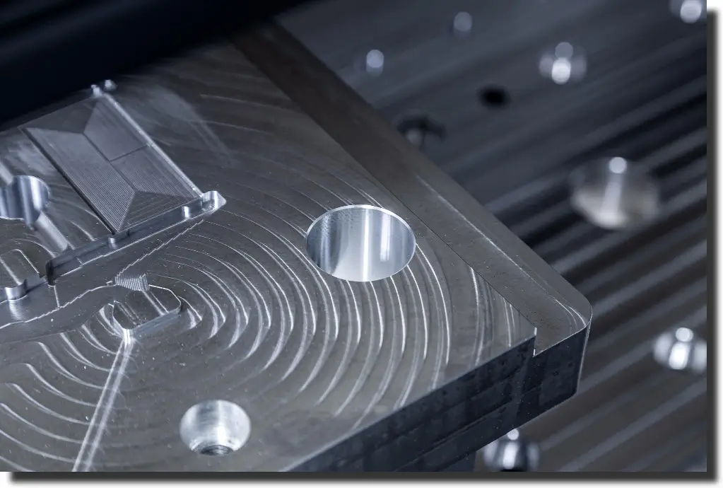
Machining carbon fiber composites requires a different cutting strategy because CFRP combines abrasive fibers, a polymer matrix, and directional properties. Fiber orientation and relatively poor thermal conductivity affect cutting behavior, tool wear, and edge quality.
The analyses in the Journal of Materials Research and Technology connect CFRP anisotropy, abrasive fibers, cutting conditions, tool wear, and machined surface quality – useful context when selecting a process around dimensional accuracy and edge integrity.
Damage is not limited to a rough-looking edge. Poorly controlled drilling or milling can introduce delamination, cracking, fiber breakout, matrix damage, or dimensional error. For structural carbon fiber components, those features often sit exactly where fasteners, inserts, brackets, or mating parts transfer load.
Composite molding establishes most of the geometry, but post-mold work completes the part. The required machining depends on the remaining features: a carbon fiber skin may need only a controlled perimeter and mounting holes, while a housing may require cutouts and machined interfaces.
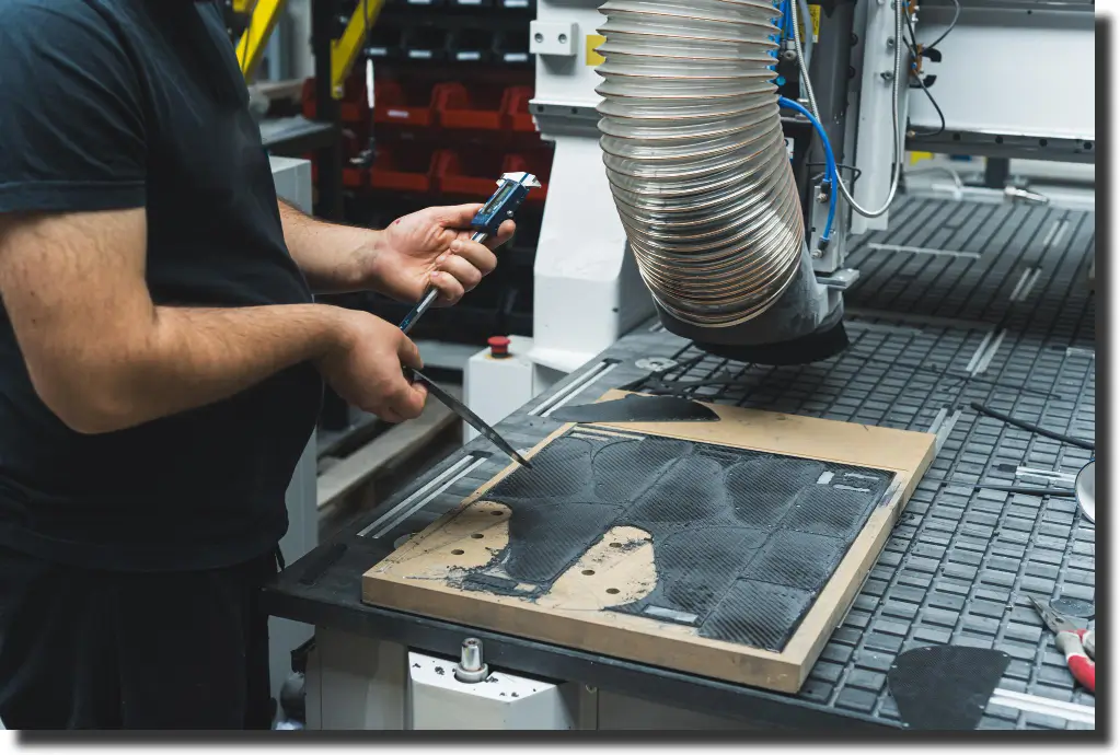
Post-mold trimming removes flash and excess material while defining the final perimeter. Edge quality matters because fraying, cracking, fiber breakout, or local delamination can create fit or structural problems around interfaces.
For that reason, the machining plan needs to control both dimensions and laminate condition. AMC's 5-axis CNC trimming capability is used for complex components where curved geometry, multiple surfaces, and tighter tolerance requirements make consistent automated trimming valuable.
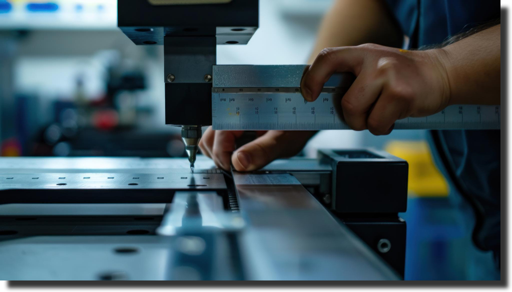
Many carbon fiber parts require holes and cutouts for fasteners, inserts, access, or mounting. Diameter alone is not enough: position, edge condition, breakout, and surrounding laminate integrity must also align with the datum structure and assembly requirements.
Some molded components need selected surfaces brought to their final tolerance after cure. Mating faces, local interfaces, datum features, or areas that interact with other hardware may need additional machining even when the surrounding geometry remains as molded.
Compression-molded components are a useful example. The manufacturing route described in Forged Carbon Fiber Strength produces complex near-net-shape parts, but gates, flash, edges, and selected critical surfaces can still require finishing operations before the component reaches final geometry.
Geometry, tolerance, access, and production volume determine the most practical carbon fiber machining route. A carbon fiber machining service should not force a flat panel, a curved structural shell, and a prototype with difficult access through the same process.
AMC uses 5-axis CNC, 3-axis CNC, and manual trimming depending on what the finished component requires.
Five-axis equipment combines X, Y, and Z movement with two rotational axes, giving the cutting tool access to curved and multi-faceted parts without repeated repositioning.
For carbon fiber CNC machining, fewer setups reduce opportunities for datum shift and accumulated variation when profiles, holes, and edges across several orientations must remain related.
Complex access only matters if the laminate survives the cut. AMC uses specialized tooling and machining techniques intended to keep composite edges clean and avoid defects such as delamination, cracking, and fraying.
The cutting strategy has to account for the material at the edge. Tool condition, part support, laminate orientation, and toolpath all influence how the fibers separate from the surrounding material.
A clean edge also gives inspection a meaningful feature to evaluate. The Composite Inspection process checks trimmed edges, hole locations, surface condition, dimensions, and other critical interfaces against the requirements of the finished component.
Five-axis trimming is most useful when complex geometry would otherwise require several setups. Curved shells, multi-sided housings, aerodynamic surfaces, and structural covers are typical examples.
AMC also identifies 5-axis trimming as a strong fit for medium- to large-scale runs where repeatability matters.
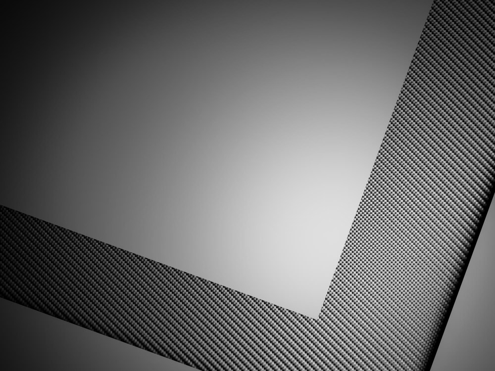
Machining carbon fiber sheets usually presents a simpler access problem, but dimensional control remains important. Straight perimeters, cutouts, slots, and mounting patterns can determine how the panel fits into a much larger assembly.
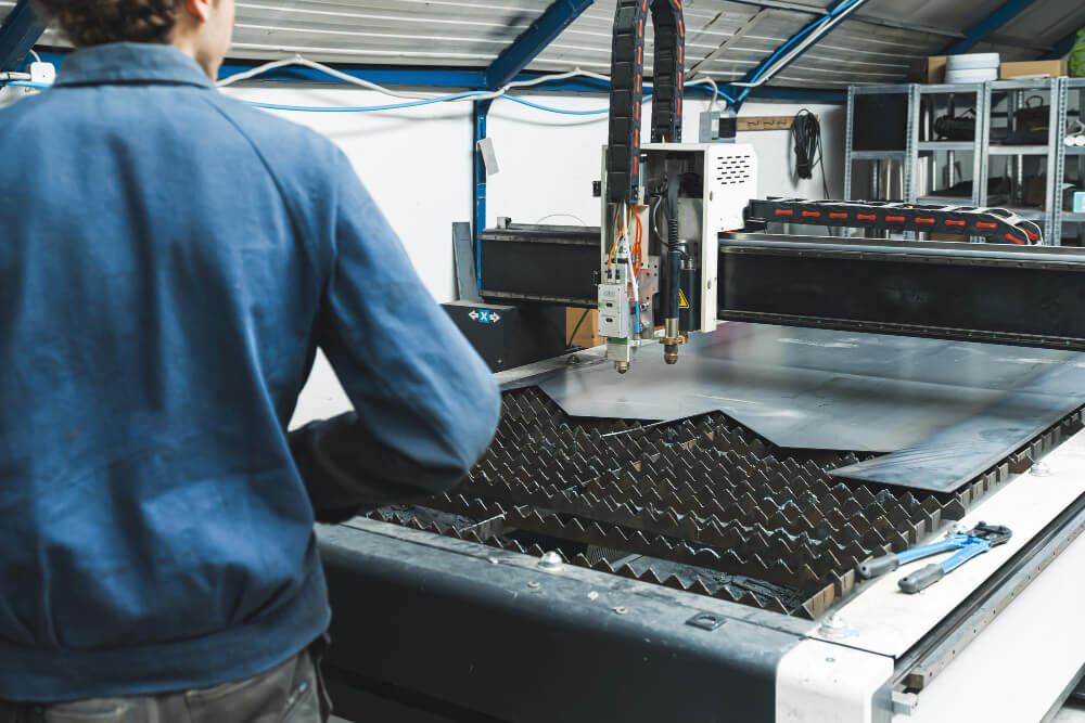
AMC uses 3-axis CNC trimming for less complex parts where movement along X, Y, and Z is enough to reach the required geometry. It is particularly suited to flat panels, straight edges, and simple cutouts.
The value here is controlled material removal without adding machine complexity that the part does not need. A straightforward setup can support both prototype work and repeat production when the geometry remains accessible from the required directions.
Finishing the machining operation does not confirm the finished geometry. Overall dimensions, cutout locations, hole positions, edge condition, and other specified features still need to be checked against the drawing or model.
AMC's Machining Inspection process can include dimensional verification using metrology methods such as CMM, along with surface inspection for tool marks, roughness, and other specified conditions.
Clean machining comes from controlling the interaction between the tool and the laminate. No single feed, cutter, or toolpath is appropriate for every carbon fiber construction.
The part must remain stable during material removal. Predictable fixturing and clear access to critical features help control geometry and make repeat machining and inspection easier.
Tool selection depends on the composite construction and operation. Because carbon fiber is abrasive, tool condition directly affects cutting forces, surface integrity, and dimensional control.
Milling a perimeter, drilling a mounting pattern, and cutting a panel opening place different demands on the tool, so the cutting strategy should be matched to the feature and required geometry.
The cutting tool does not encounter the same material response around every edge. Fiber direction changes relative to the cutting path, and the resin matrix responds differently from the reinforcement.
That is why identical geometry can machine differently when laminate architecture changes. Continuous woven material, unidirectional reinforcement, and chopped compression-molded carbon do not create the same edge conditions.
For engineers developing custom carbon fiber parts, machining requirements should therefore be considered alongside fiber architecture and process selection rather than added only after the laminate has been finalized.
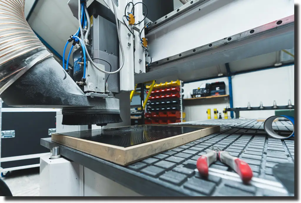
Tight tolerance work begins before the cutting tool touches the laminate. The print, molded geometry, datum strategy, tooling, fixturing, and inspection plan all determine how much control the CNC process can realistically maintain.
AMC prefers early involvement through Design for Manufacturability so geometry, materials, manufacturing route, and assembly requirements can be reviewed before production decisions are locked.
For machining, that means identifying critical dimensions, accessible datums, hole and cutout locations, mating surfaces, and realistic tolerance requirements early. A feature that is difficult to fixture, reach, or measure will remain difficult after the mold is complete.
Our in-house design capabilities also include CAD modeling, structural analysis, reverse engineering, 3D scanning, and metrology. These tools help connect the digital definition of the component with the manufacturing route that has to reproduce it.
Machining can establish edges and local features, but it should not be expected to correct uncontrolled molded geometry across an entire part. The closer the molded component is to the intended shape, the more efficiently post-processing can focus on the features that actually need cutting.
AMC's machined molds and tooling capabilities include 3-axis, 5-axis, and lathe machining for tooling and custom components. Keeping mold geometry and downstream machining requirements connected gives the production team a clearer dimensional path from tool surface to finished part.
A repeatable toolpath cannot compensate for inconsistent part location. The component needs a controlled relationship to its datums every time it enters the machining setup.
That means the machining plan has to define how the part will be supported, located, accessed, and measured. For production work, those decisions affect more than the first acceptable component – they determine whether the same geometry can be reproduced across the run.
Machining is complete only when the resulting geometry and edge condition can be verified. Carbon fiber machining quality therefore includes both dimensional requirements and the condition of the laminate around the feature.
Visual inspection can identify exposed cracking, fraying, tool marks, and other surface conditions. Dimensional verification can confirm hole locations, edge positions, profiles, and mating features. When internal integrity is part of the acceptance requirement, additional inspection methods may be needed.
The inspection plan should focus on features that control fit and performance. A cosmetic edge, structural mounting hole, and precision mating surface do not need identical acceptance criteria.
Carbon fiber machining works best when it is connected to the stages before and after it. AMC integrates design, tooling, composite manufacturing, trimming, finishing, assembly, and inspection so final dimensions are not treated as an isolated CNC requirement.
A typical workflow can include:
Keeping these stages connected helps prevent a machining decision from creating fit, laminate, or assembly problems downstream.
A capable carbon fiber machining service needs more than CNC capacity. The machining partner should understand how molded composite geometry, laminate construction, fixturing, tool access, edge quality, and inspection interact.
Before selecting a supplier, review whether the manufacturing team can:
Machining capability should therefore be evaluated against the actual part rather than the machine list alone.
Use this checklist to keep machining requirements aligned with the finished component:
Machining carbon fiber requires more than removing excess material. Clean edges and tight tolerances depend on laminate construction, molded geometry, part support, machining strategy, and inspection. Five-axis, 3-axis, and manual trimming each fit different geometry, tolerance, and production requirements.
At AMC Composites, machining is integrated with design, tooling, composite manufacturing, finishing, assembly, and inspection. We’d love you to contact us to review your print, machining features, tolerance requirements, and production volume, and define a manufacturing path built around the finished carbon fiber part.
.webp)