Making a carbon fiber part starts with getting the mold right. One approach is to make a mold from a pattern; another is to machine it directly from tooling board or metal. The goal is to produce accurate, durable tooling with a high-quality surface finish that can handle the intended production run.
At AMC Composites, we manufacture molds and tooling for custom carbon fiber parts, from lightweight shells to more complex forged components. There are several ways to produce the parts themselves, including prepreg, vacuum infusion, wet layup, and compression molding. Each involves different materials, tooling, and curing conditions. We'll look at how composite molding works, which methods are available, and where they make sense in production.

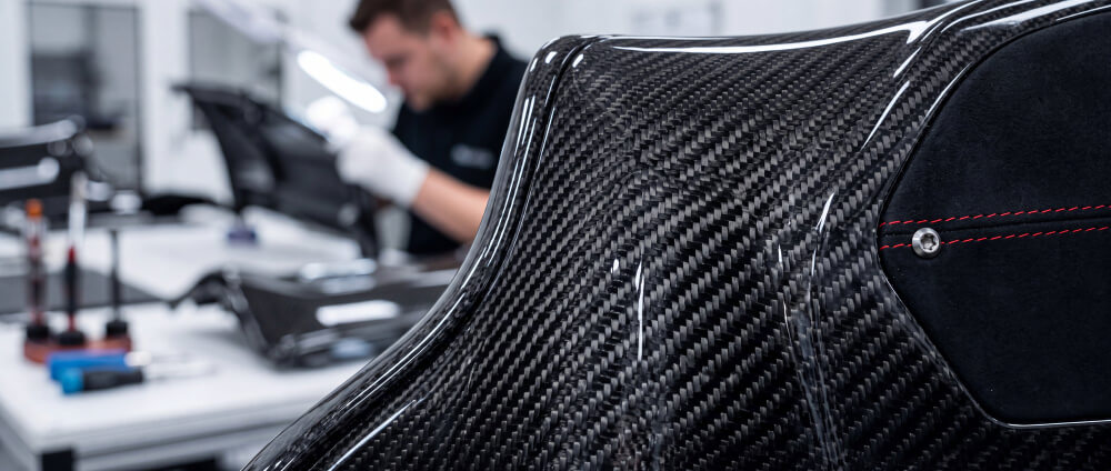
Take a lightweight carbon fiber shell with tight curves and corners. The fabric needs to sit firmly against the mold surface without bridging across the contours. If it doesn't, the tool may have the right shape, but the finished laminate won't follow it as intended.
The mold surface also needs attention. Marks or imperfections can transfer to the finished part, which is why tooling must be prepared to the required surface standard. Then comes the layup itself. Fiber orientation, resin content, and curing conditions all affect the result, even when the same mold is used.
For prototypes, there may still be room to adjust the design before committing to production tooling. When making repeated batches, the goal is to get the same geometry and laminate quality from one part to the next. Through our Design & Development services, we review part geometry, radii, demolding access, and material placement early, before these details become problems on the production floor.

The composite molding process starts with a clean mold and a plan for how the material will fit inside it. Once the tool is ready, the surface is checked and treated with a suitable release agent. For fabric-based methods, carbon fiber is cut to the required shapes and placed in the mold according to the layup schedule. Compression molding uses a prepared charge of chopped carbon fiber instead. In volume production, pre-cut fabric helps keep the layup consistent from one part to the next.
What happens next depends on the material being used. Prepreg already contains resin, while dry carbon fiber needs resin introduced during layup or infusion. Depending on the method, the material may be vacuum-bagged, compressed, or cured under other specified conditions. Temperature, pressure, and cure time must suit the particular resin system.
After curing, the part can be released from the mold. It may look close to finished, but there is often more work to do. Excess material around the edges needs trimming, holes or mating surfaces may require machining, and visible carbon fiber surfaces can go through Composite Finishing. The part is checked before moving on to the next manufacturing stage.
Different composite molding techniques manage fiber placement, resin introduction, and consolidation in different ways. The choice affects tooling demands, production speed, geometric flexibility, and how consistently the resulting laminate meets specifications.
Prepreg uses carbon fiber reinforcement that has already been impregnated with a controlled amount of resin. The material is positioned in the mold according to the specified ply sequence and fiber orientation.
Depending on the resin system and application, curing may involve an autoclave or an elevated-temperature process. Controlled resin content and laminate placement make prepreg suitable for structural components where weight, stiffness, and directional properties are closely specified.
The process still requires careful layup. Wrinkles, misplaced plies, and unsuitable cure conditions can affect the final component despite the controlled starting material.
Vacuum infusion begins with dry carbon fiber fabric arranged inside a mold. A sealed vacuum bag removes air and compacts the reinforcement before liquid resin is drawn through the fiber stack.
Resin flow requires planning around part geometry. Inlet placement, flow paths, corners, and laminate thickness influence whether the reinforcement becomes fully saturated. Proper vacuum control and curing help manage resin distribution and void content.
This method is particularly useful for larger carbon fiber panels, shells, and covers, where the size and shape of the component make resin delivery and tooling strategy important.
Wet layup introduces liquid resin directly to dry reinforcement as the material is placed in the mold. Technicians position the fabric and saturate the layers during the layup process.
The approach offers flexibility for prototypes, custom shapes, and low-volume production without requiring the same level of process infrastructure as more automated routes.
Resin content and consolidation depend more heavily on manual process control, making inspection and realistic performance requirements particularly important.
Forged carbon uses chopped carbon fiber combined with resin to form a charge that is placed inside a mold and consolidated under elevated temperature and pressure.
Unlike continuous-fiber laminates, the chopped reinforcement can flow into complex features during molding. This makes forged carbon attractive for brackets, housings, structural covers, and other smaller components with ribs, pockets, or intricate geometry.
Charge placement and material flow still influence fiber distribution. Research published in Composites Part A: Applied Science and Manufacturing demonstrates how sheet molding compound flow can alter woven prepreg fiber alignment in hybrid compression molding. The findings help explain why material flow and fiber placement need to be considered together.
For production applications, the combination of part geometry, tool design, and processing conditions determines whether this route is suitable. Forged Carbon Fiber Strength examines how chopped-fiber architecture, complex shapes, and repeatable manufacturing relate.

A woven carbon fiber laminate and a chopped-fiber charge may use similar reinforcement materials, but they behave differently during molding and under load. Reinforcement architecture and resin system need to suit both the application and the manufacturing method.
The matrix holds the reinforcement together and transfers loads between fibers. Epoxy systems are widely used for carbon fiber components, while other resin chemistries may be selected according to chemical exposure, processing conditions, or required temperature resistance.
Kevlar and fiberglass provide additional reinforcement options. Kevlar may be appropriate where impact and abrasion behavior matter, while fiberglass offers an economical solution for selected components and prototypes. Each reinforcement must be evaluated against the part's mechanical requirements rather than treated as interchangeable with carbon fiber.

The material used to manufacture a mold is a separate decision from the reinforcement used in the finished component. Expected production volume, processing temperature, part geometry, and required tool life all influence the choice.
AMC's Mold Making & Machining capabilities include fiberglass, tooling board, and metal molds for different manufacturing requirements.
Fiberglass molds provide a reusable tooling option for low-to-medium-volume work. They can support repeated production without the cost of metal tooling when operating conditions and geometry permit.
Tooling board is relatively easy to machine, making it useful for prototype molds, short production runs, and geometries that may require adjustment during development.
Its main advantage is the ability to create and refine tooling before committing to a longer-life production mold. Temperature limits and expected cycle count must remain compatible with the selected material.
Metal molds offer durability and thermal stability for repeated manufacturing cycles and processes involving elevated temperatures or pressure.
They are commonly used in multi-part tooling, including molds for hollow components and forged carbon fiber parts.
A molded carbon fiber component can only reproduce the geometry that its tooling supports. Cavity dimensions, parting lines, radii, draft angles, and release access all influence whether the part can be formed and removed without unnecessary damage or rework.
Tool surface condition also affects the molded finish. Subsequent Surface Preparation (Sanding) may refine minor irregularities, but it cannot correct defects within the laminate.
AMC uses 3-axis, 5-axis, and lathe machining for molds, tooling, and related components. This supports the production of complex mold surfaces, assembly jigs, and tooling intended for repeated use.
Our carbon fiber tooling guide explains how tool design supports consistent composite production.
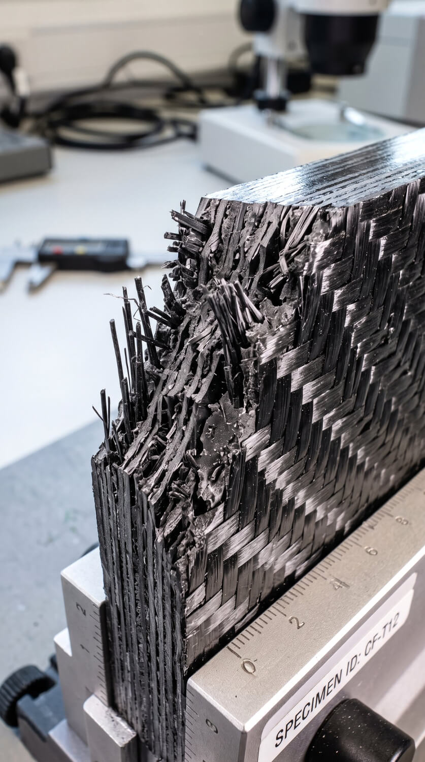
Once a carbon fiber part comes out of the mold, the first checks focus on its surface, dimensions, and visible laminate condition. Wrinkles, dry areas, cracks, or signs of delamination may indicate problems with material placement, resin flow, or processing conditions.
Not every issue is visible from the outside. Depending on the component's requirements, Composite Inspection can include dimensional measurements, visual checks, and non-destructive testing to evaluate internal integrity. The inspection method is selected according to what the finished part needs to meet, rather than applying the same tests to every component.
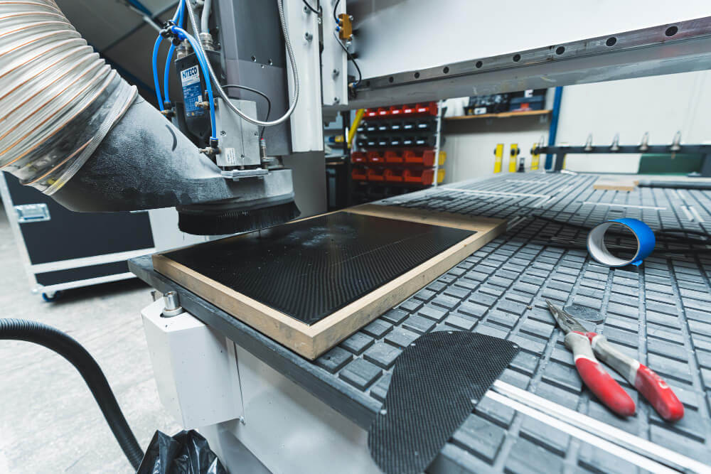
A mold can meet its CAD dimensions and still create problems downstream if layup access, trim allowances, or assembly interfaces were not considered during design.
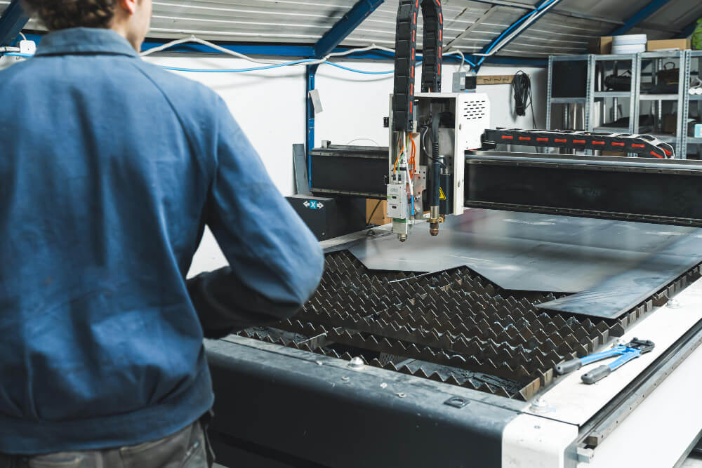
For repeat production, Kit Cutting prepares carbon fiber plies in predefined shapes and orientations, reducing material waste and improving layup consistency. After curing and demolding, Composite Trimming removes excess material and establishes final edges, holes, and cutouts.
Finishing, assembly, and inspection complete the workflow where required. Keeping these operations connected allows molded composite parts to move from tooling to final verification with geometry, surface requirements, and critical interfaces addressed throughout production.
Before selecting a molding route, confirm the requirements that will influence tooling, material selection, and production:
Choosing a composite molding method means finding the right match between the material, mold, part geometry, and expected production volume. Getting those decisions right early makes it easier to produce carbon fiber components that meet their intended specifications.
AMC Composites brings mold making, composite manufacturing, machining, finishing, and inspection together within one production workflow. Connect with us to discuss your project, material requirements, and production goals.