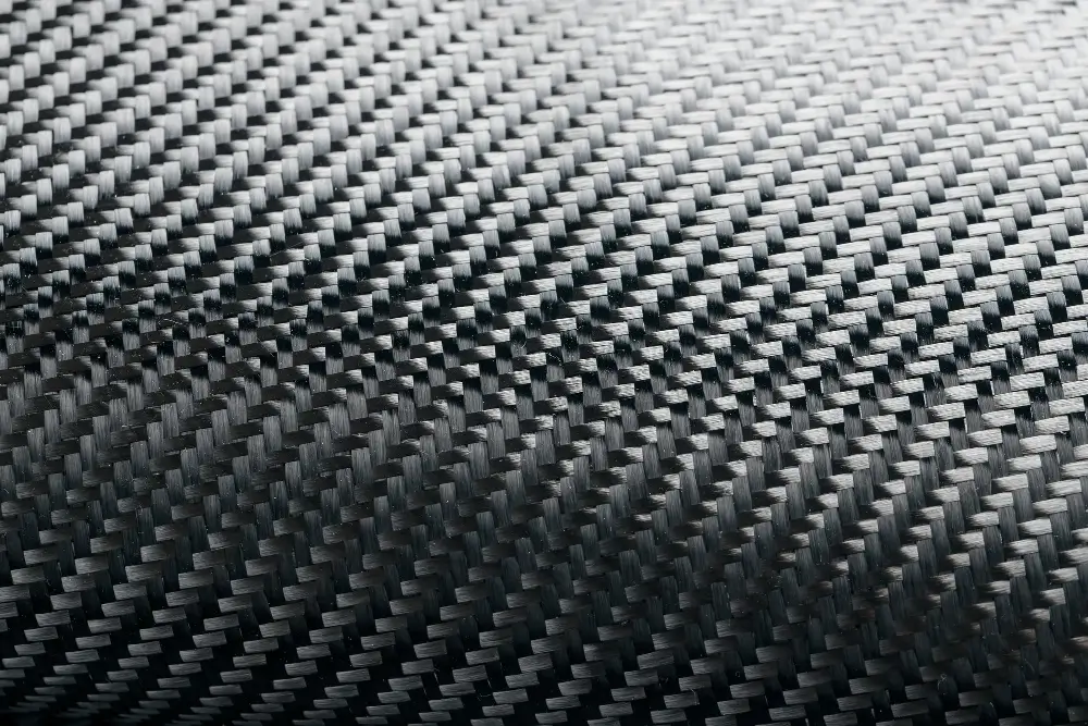
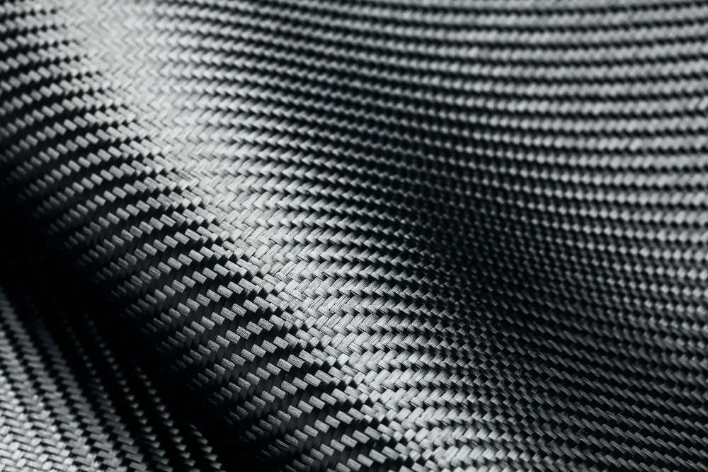
A carbon fiber part can leave the mold with a clean finish yet not meet specifications. Dimensional inaccuracy, internal voids, microfractures are common reasons for inspection failure. Surface appearance alone cannot confirm dimensional accuracy, laminate condition, edge quality, bond integrity, or functional fit.
Composite inspection is a manufacturing requirement, not a final step. The inspection plan links the print, duty case, tolerances, interfaces, and acceptance criteria directly to the finished part.
At AMC Composites, inspection strategy is driven by the part. Carbon fiber panels, wheels, housings, brackets, bonded assemblies, and custom carbon fiber parts each present different risks. Inspection methods are selected around construction, geometry, and application requirements.
Final acceptance is too late to decide what should have been measured. Critical dimensions, surface requirements, bond zones, mounting interfaces, and functional checks need to be defined before the part moves through tooling, molding, trimming, finishing, and assembly.
Early planning also determines whether each feature can be inspected reliably. A tolerance has limited value if the datum is unclear, the measurement point becomes inaccessible after assembly, or the inspection method cannot detect the defect that matters. The drawing, digital model, process route, and acceptance criteria need to support one another.
AMC works with the customer to establish quality guidelines around the application. A cosmetic cover may require close control of finish, trim, and fit. A structural carbon fiber component may also require dimensional verification, inspection of critical interfaces, and internal evaluation, where the duty case supports it.
This approach keeps inspection tied to actual risk. It also gives the manufacturing team clear requirements before production begins, reducing late revisions and disagreements over final acceptance.
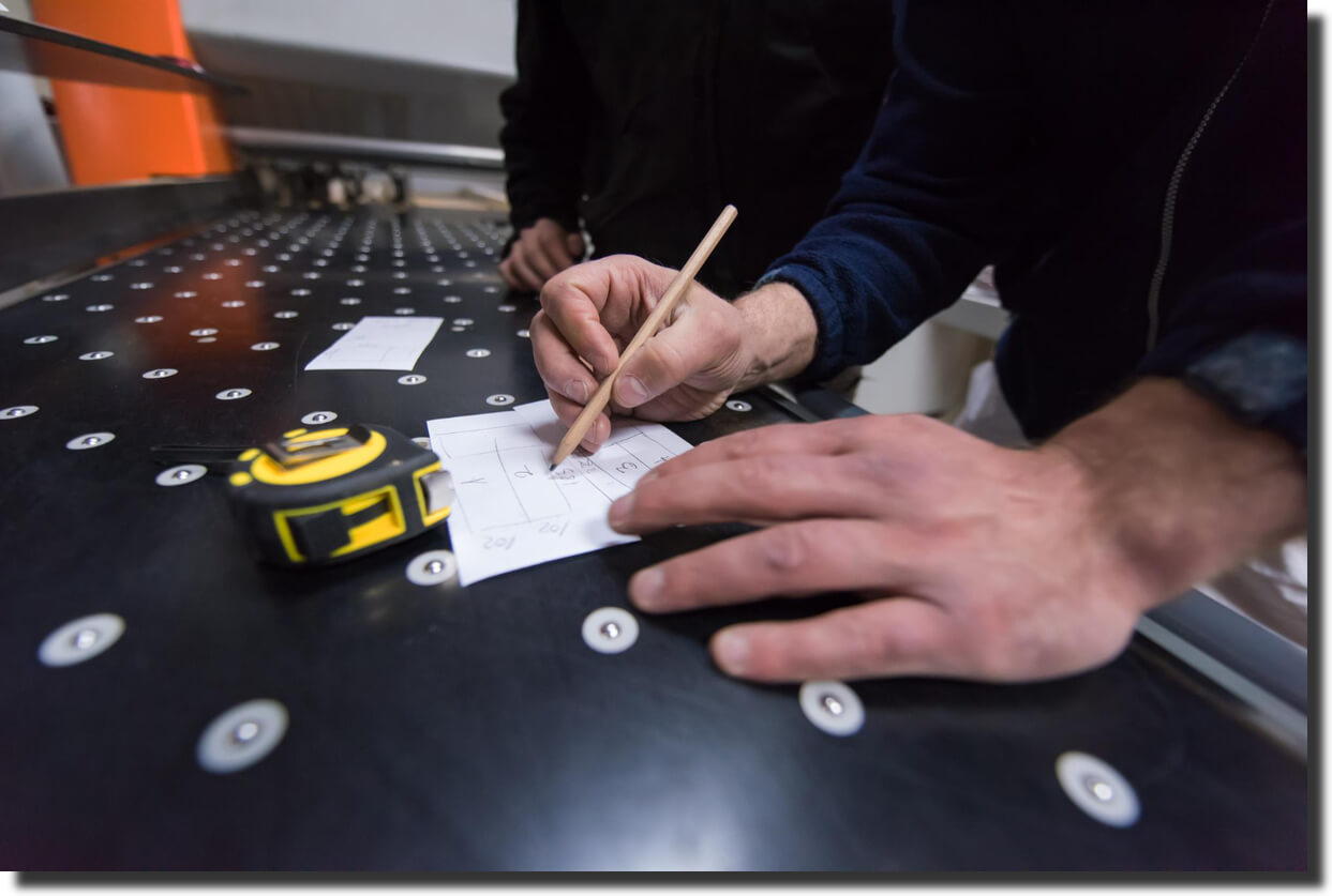
Composite quality inspection checks if the finished part meets the requirements that control its use. These requirements fall into three areas:
Structural checks look for indications such as cracking, delamination, voids, fiber damage, or bond irregularities when those conditions are relevant to the part. Not every issue is visible from the surface, so the inspection plan may combine visual checks with an appropriate non-destructive method.
Dimensional verification confirms that the component matches the drawing or model. Overall profile, thickness, hole locations, cutouts, mounting points, datums, and assembly interfaces can all affect whether the part fits and carries load as intended.
Surface and edge checks address finish defects, machining marks, roughness, cracks, damaged trim lines, and visible laminate irregularities. Inspection criteria also change with material architecture. Continuous laminates, sandwich panels, and compression-molded components do not present identical risks; the construction discussed in Forged Carbon Fiber Strength is one example of why acceptance requirements must follow the actual part.

No single method can verify every condition in a composite component. Composite inspection techniques differ in what they measure, how deeply they evaluate the material, and which geometries they can inspect effectively.
AMC selects the method based on the part requirements. Visual inspection may be sufficient for a surface finish or exposed trim edge. Complex geometry may call for laser scanning or CMM measurement. Internal indications can require ultrasonic or X-ray testing when specified for the program.
Visual inspection is the first practical check for many carbon fiber components. An experienced technician can evaluate visible cracks, surface voids, wrinkles, exposed delamination, finish irregularities, contamination, tool marks, and damage around edges or drilled features.
Visual inspection is fast and practical, but its limits are clear. A clean surface does not confirm the laminate condition below. Low-velocity impact can leave little external evidence while causing internal delamination.
Visual findings guide the next step. If a surface indication suggests deeper damage, dimensional analysis or a suitable Non-Destructive Testing (NDT) method may be required before acceptance.
Laser scanning and coordinate measuring machines serve different dimensional needs. A laser scanner captures complex surfaces and produces a broad digital representation of the part. That data can reveal profile variation, warpage, trim deviation, and differences between the manufactured geometry and the reference model.
A Coordinate Measuring Machine (CMM) measures defined points and features with high precision. It is well-suited to datums, hole locations, bores, mounting interfaces, edge positions, and other controlled dimensions on the drawing.
Method selection depends on geometry and tolerance. Large contoured panels benefit from broad surface data, while machined interfaces require targeted point measurement. The same logic applies to Machining Inspection, where tool surfaces and finished features are checked against specified parameters.
Internal defects require methods that can evaluate the component without cutting or otherwise compromising it. Ultrasonic or X-ray testing can be employed when the application requires evaluation for delamination, porosity, inclusions, debonding, or other internal discontinuities.
Method selection is driven by defect type, depth, fiber orientation, laminate thickness, and part geometry. Ultrasonic inspection is effective for internal laminate conditions. Radiographic methods provide a different view of internal structure. No single method is universal for every carbon fiber part.
A review in the Journal of Materials Research and Technology connects common FRP failure modes with the capabilities and limitations of different NDT systems. The comparison is useful when selecting a method for a specific defect location, construction, and service condition.
A dimensionally correct component can still fail the assembly check. Complete bonded carbon fiber assemblies need verification at the interfaces where separate parts, inserts, adhesives, fasteners, and functional systems come together.
Fit and alignment testing confirms that components are located correctly without forcing the assembly or creating unintended preload. Bond verification evaluates connection quality, adhesive distribution, and strength when required by the specification. The exact method depends on the bond design and acceptance criteria.
Functional testing is performed when required for assemblies with mechanical or electrical features. Movement, engagement, alignment, clearances, and operation are evaluated before delivery. These checks confirm that components work together as intended.
Large surfaces can hide small deviations that become costly if discovered late. Composite panel inspection must cover more than appearance. Profile, flatness, trim, holes, inserts, bond lines, and local reinforcements all influence fit and service performance.
The inspection plan must match panel construction. A monolithic carbon fiber skin, sandwich panel, bonded cover, and machined enclosure may look similar but require different checks.
Composite panels can develop warpage, spring-back, profile variation, or local thickness changes during molding and curing. A visually smooth panel may still sit outside the required geometry or fail to align with the surrounding structure.
Laser scanning can compare broad panel surfaces with the digital model, while CMM or other metrology methods can verify defined datums and critical locations. Depending on the drawing, inspection may cover flatness, contour, thickness, overall dimensions, and the relationship between mounting features.
Surface quality is evaluated separately from geometry. Inspection before and after carbon fiber surface finishing checks finish consistency, visible resin variation, cracks, impressions, contamination, and other surface conditions against customer requirements.
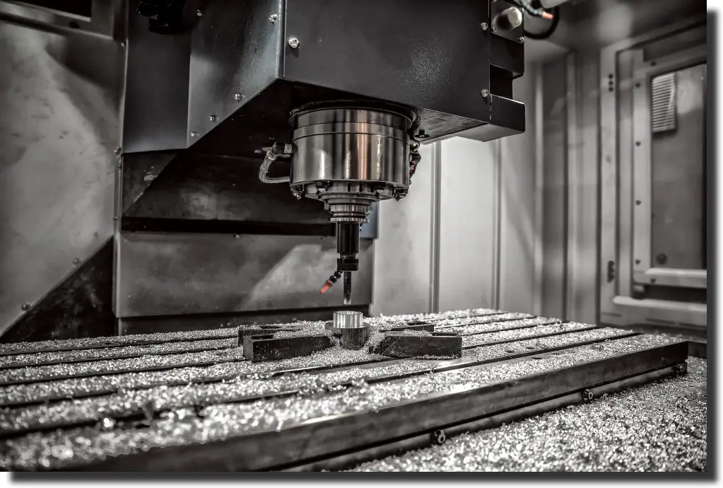
Cutouts and mounting areas concentrate both manufacturing risk and service loads. Controlled carbon fiber trimming and drilling define the panel boundary and create features that must align with inserts, fasteners, brackets, or the next assembly.
Poor machining can introduce chipped edges, cracks, fiber breakout, or delamination around holes. Incorrect locations can also force the assembly out of alignment, even when the rest of the panel meets its profile requirement.
Inspection must verify cutout geometry, edge condition, hole size and position, local reinforcement, inserts, and mounting interfaces. These are functional features, not cosmetic details.
Bonded and sandwich panels introduce interfaces that are not present in a simple monolithic laminate. Skins, cores, adhesive layers, bonded doublers, closeouts, and embedded inserts must work together without gaps, local separation, or unintended geometry changes.
Visual and dimensional checks can confirm accessible bond lines, fit, panel profile, edge closeouts, and insert locations. Internal evaluation may be required where the project needs confirmation of skin-to-core adhesion, subsurface debonding, or other hidden conditions.
The inspection plan changes with what AMC is delivering. A molded carbon fiber component, a bonded assembly, and a machined tool carry different risks, so each requires its own measurements, acceptance criteria, and verification methods.
A carbon fiber housing may pass its surface inspection but still require verification of hole positions and mounting datums. A complete assembly adds another layer of risk because inserts, bonded joints, mechanical features, and surrounding components must align correctly. Machined molds and tools also require accurate geometry because variation at the tooling stage can be transferred into every part produced from that surface.
Composite quality is built during production, not created by final inspection. Inspection confirms the result, but repeatable carbon fiber parts depend on controlling the steps that define the laminate, interfaces, and finished geometry.
The inspection plan must follow these risk areas. A complex structural component may need checks at multiple production stages. A lower-risk cosmetic part may require only focused dimensional and visual verification.
At AMC Composites, inspection is connected to the entire production plan. Design services, tooling, molding, composite trimming, finishing, assembly, and quality verification are treated as related steps so that requirements remain consistent from the customer’s print to the delivered component.
Quality requirements begin with the application. AMC works with the customer to define the dimensions, tolerances, surface expectations, functional features, and critical interfaces that need to be verified.
These guidelines may include:
This process keeps inspection relevant to the actual part. A visible carbon fiber trim component does not need the same verification plan as a load-bearing aerospace panel or a bonded automotive assembly. Requirements are set around function, risk, and customer expectations.
Inspection can begin before the first production component is molded. Machined tools and mold surfaces may be measured to confirm geometry, critical features, and finish before they begin influencing repeat production.
Once molding starts, inspection follows the component through the stages that affect final quality:
Inspection at the correct stage makes problems easier to isolate. It also helps prevent a dimensional issue, damaged edge, or misaligned insert from moving into finishing or final assembly.

Use this checklist before production begins:
Composite inspection connects design intent with the finished part. Visual inspection, laser scanning, CMM measurement, applicable NDT, bond verification, and functional testing each answer different quality questions. No single method can confirm every dimension, interface, surface condition, or internal feature in a carbon fiber component.
The strongest inspection plan begins before production and follows the part through tooling, molding, trimming, finishing, and assembly. Contact AMC Composites to review your print, confirm the duty case, and define a manufacturable path with an inspection plan for repeatable performance.
.webp)